Medical Imaging and Reverse Engineering

In the field of biomedical engineering, reverse engineering is used to reconstruct physical models in the form of computer data (virtual models) without the assistance of conceptual drawings, specifications, or technical drawings of the product design. This involves the phase of data collection which is achieved through the scanning of physical components by medical imaging techniques. Due to the demands of production time and complexity, rapid prototyping can then be applied to fabricate geometries matching those of the human body, which is often irregular, complex, and unique in shape. With rapid prototyping replacing some of the conventional manufacturing processes, the efficiency of the whole process of production can be boosted.
This is a preview of subscription content, log in via an institution to check access.
Access this chapter
Subscribe and save
Springer+ Basic
€32.70 /Month
- Get 10 units per month
- Download Article/Chapter or eBook
- 1 Unit = 1 Article or 1 Chapter
- Cancel anytime
Buy Now
Price includes VAT (France)
eBook EUR 93.08 Price includes VAT (France)
Hardcover Book EUR 116.04 Price includes VAT (France)
Tax calculation will be finalised at checkout
Purchases are for personal use only
References and Further Reading
- Rooppakhun, S., Nattapon, C., Kriskrai, S.: Advanced Medical Imaging and Reverse Engineering Technologies in Craniometric Study. IntechOpen (2011) Google Scholar
- Mikla, V.I., Mikla, V.V.: Medical Imaging Technology. Elsevier, Waltham, MA, USA (2013) ChapterGoogle Scholar
- Hendee, W.R., Russell Ritenour, E.: Medical Imaging Physics. Wiley, New York (2003) Google Scholar
- Lisle, D.A.: Imaging for Students. Hodder Arnold, London (2012) BookGoogle Scholar
- Dance, D.R., Christofides, S., Maidment, A.D.A., McLean, I.D., Ng, K.H.: Diagnostic Radiology Physics: A Handbook for Teachers and Students. International Atomic Energy Agency, Vienna (2014) Google Scholar
- Lantada, A.D.: Handbook on Advanced Design and Manufacturing Technologies for Biomedical Devices. Springer, Boston (2013) BookGoogle Scholar
- Du Boulay, G.H.: Principles of X-Ray Diagnosis of the Skull. Butterworth-Heinemann. Oxford, UK (2016) Google Scholar
- Wong, K.K.L.: Methods in Research and Development of Biomedical Devices. World Scientific, Singapore (2013) BookGoogle Scholar
- Chua, C.K., Leong, K.F., Lim, C.S.: Rapid Prototyping: Principles and Applications. World Scientific, Singapore/Hackensack (2010) BookGoogle Scholar
- Gibson, I.: Advanced Manufacturing Technology for Medical Applications: Reverse Engineering, Software Conversion and Rapid Prototyping. Wiley, Chichester (2006) Google Scholar
- Bushberg, J.T., Boone, J.M.: The Essential Physics of Medical Imaging. Lippincott Williams & Wilkins, Philadelphia (2011) Google Scholar
- Gibson, I., Rosen, D.W., Stucker, B.: Additive Manufacturing Technologies. Springer, New York (2014) Google Scholar
- Ségonne, F., Dale, A.M., Busa, E., Glessner, M., Salat, D., Hahn, H.K., Fischl, B.: A hybrid approach to the skull stripping problem in MRI. NeuroImage. 22, 1060–1075 (2004) ArticleGoogle Scholar
- Wurm, G., Lehner, M., Tomancok, B., Kleiser, R., Nussbaumer, K.: Cerebrovascular biomodeling for aneurysm surgery: simulation-based training by means of rapid prototyping technologies. Surg. Innov. 18, 294–306 (2011) ArticleGoogle Scholar
- Lee, J.W., Ahn, G., Kim, D.S., Cho, D.W.: Development of nano-and microscale composite 3D scaffolds using PPF/DEF-HA and micro-stereolithography. Microelectron. Eng. 86, 1465–1467 (2009) ArticleCASGoogle Scholar
- Arcaute, K., Mann, B.K., Wicker, R.B.: Stereolithography of three-dimensional bioactive poly (ethylene glycol) constructs with encapsulated cells. Ann. Biomed. Eng. 34, 1429–1441 (2006) ArticleGoogle Scholar
Author information
Authors and Affiliations
- Department of Biomedical Engineering, City University of Hong Kong, Hong Kong, Hong Kong Raymond H. W. Lam
- Department of Mechanical and Aerospace Engineering, Department of Biomedical Engineering, New York University, Brooklyn, NY, USA Weiqiang Chen
- Raymond H. W. Lam
You can also search for this author in PubMed Google Scholar
You can also search for this author in PubMed Google Scholar
Problems
Problems
1.1 Problem 7.1
Please answer the following questions according to Table 7.P1.
- (a) Complete Table 7.P1 by filling in the missing values.
- (b) Find the intensity reflection coefficient at the interface between A and B.
- (c) An ultrasound wave of intensity 0.08 W m −2 in medium A comes across the interface between A and B. Calculate the intensity of the ultrasound wave entering medium B.
- (d) An interface can be formed by any two media above. Which of these interfaces will cause the greatest proportion of the incident ultrasound to reflect?
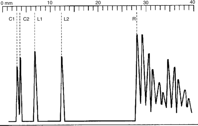
- (a) Estimate the length of the eyeball from the display.
- (b) Explain why two spikes are obtained from each of the cornea and the lens.
- (c) In the study, the computed thickness of the cornea is found to be 576 μm.
- Estimate the time interval between receiving spikes C1 and C2 by the computer.
- What is the maximum pulse length required to produce the above result?
- Calculate the minimum frequency used by the ultrasound machine.
- Sketch the resulting display if the frequency of ultrasound used is too low.
- (d) A student said that due to attenuation, the pulses received later should have lower peaks. Suggest a reason to explain why the peaks of the pulses do not decrease gradually.
- (e) A series of pulses appears on the right side of R. Suggest a reason for this.
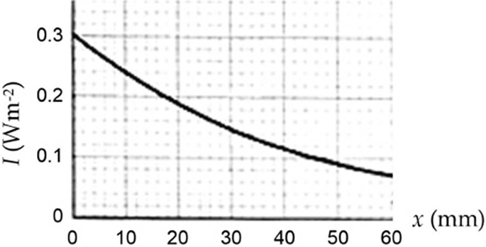
1.5 Problem 7.5
- (a) State two causes of the attenuation of ultrasound in a medium.
- (b) Find the half-value thickness and the linear attenuation coefficient of the medium for the ultrasound.
- (c) Write down an equation relating I and x.
- (d) Determine the intensity of the ultrasound at a depth of 100 mm.
- (e) Using the given axes, sketch the I-x graph if, separately,
- The initial intensity of the ultrasound is 0.5 W m −2 .
- The soft tissue is replaced by water.
- Ultrasound of a higher frequency is used.
1.6 Problem 7.6
Please reconsider Fig. 7.P2 again as the variation of intensity I of an X-ray against depth x in a medium.
- (a) Prove that the half-value thickness x1/2 is related to the linear attenuation coefficient μ by x1/2 = ln2/μ.
- (b) Find the linear attenuation coefficient (in m −1 ) of the medium.
- (c) Write down an equation relating I and x.
- (d) Calculate the depth required when the intensity falls to 0.01 W m −2 .
1.7 Problem 7.7
A beam of diagnostic X-ray of intensity 20 W m −2 and photon energy 80 keV is produced by an X-ray tube. The beam is incident on a thick lead block. The linear attenuation coefficient of lead for the X-ray photons is 58 m −1 .
- (a) All X-ray machines are remotely controlled by operators behind a shielded wall. By referring to the property of X-ray, explain why this is necessary.
- (b) Write down an equation for the intensity I of the X-ray at depth x in the lead block.
- (c) Calculate the half-value thickness of lead for the X-ray photons.
- (d) Calculate the thickness of the lead block needed to reduce the intensity of the emerging X-ray to 1%.
- (e) State what happens to the linear attenuation coefficient:
- If aluminum is used instead of lead.
- If the X-ray photon energy is reduced to 5 keV.
- (f) In practice, an X-ray tube used in radiographic imaging will produce both high energy and low energy X-ray photons. Explain why the low energy photons have to be filtered out; and suggest how to filter out these low-energy photons.
1.8 Problem 7.8
An X-ray machine produces a parallel beam of X-ray of intensity 500 W m −2 . The cross-sectional area of the beam is 0.1 mm 2 . The energy of each X-ray photon is 90 keV.
- (a) If the efficiency of the X-ray machine is 0.8%, calculate the rate of electrical energy consumed.
- (b) What is the minimum working voltage across the X-ray machine?
- (c) Express the energy of an X-ray photon leaving the X-ray machine in Joule.
- (d) The working voltage of the machine is now increased. Given that the magnitude of charge on an electron to be 1.6 × 10 −19 C, state and explain what happens to the ionizing power of the X-ray, the intensity of the X-ray leaving the X-ray machine, and the half-value thickness of lead for the X-ray.
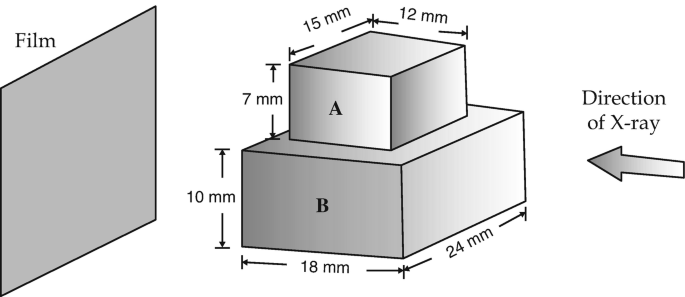
1.9 Problem 7.9
Two rectangular blocks, A and B, with the arrangement and dimensions shown in Fig. 7.P3, are placed in the path of an X-ray. μA and μB are the linear attenuation coefficients of the blocks. If there is no image contrast between A and B, roughly sketch the result on the film. Write down mathematically the condition for such situation to occur.
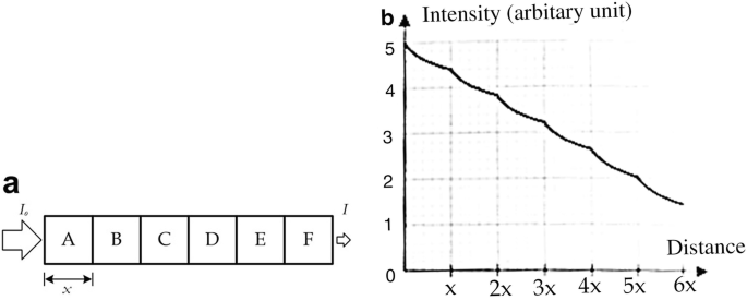
1.10 Problem 7.10
Figure 7.P4a shows an X-ray of intensity Io entering into a structure which is formed by six cubic blocks (A–F), each with a side length x. The linear attenuation coefficients of the blocks are μA, μB, …, μF, respectively.
- (a) Find the intensity I of the emerging X-ray in terms of Io, μB, …, μF and x.
- (b) Figure 7.P4b shows the variation of intensity of X-ray with the distance along the path. You may assume that after passing through each block, the intensity falls by 0.6 unit in the plot.
- Which block has the largest linear attenuation coefficient? And which has the lowest linear attenuation coefficient? Justify your answer.
- Rough sketch the variation of intensity with distance if the same X-ray enters from F and emerges from A.
- If we consider all the six blocks as a single block with a uniform linear attenuation coefficient μ such that the resultant effect (i.e., I/Io) is the same, what would this value of μ comparing to μA?
1.11 Problem 7.11
Given that the gyromagnetic ratios with values of 42.58 MHz/Tesla for 1 H, 10.71 MHz/Tesla for 13 C, and 40.05 MHz/Tesla for 19 F, please suggest a range of the resonance frequencies for an external magnetic field strength ranging from 0.1 to 2.0 Tesla. Under the same magnetic field strength, please suggest also the corresponding resonance frequencies for 13 C and 19 F.
1.12 Problem 7.12
If it takes 300 m s to obtain a single voxel in an MRI operation, how much time is required to obtain five slices with a matrix size of 256 × 256?
1.13 Problem 7.13
- (a) If a material has a horizontal relaxation time constant Tfid = 200 m s, what will the MR signal be 200 m s after an RF pulse has applied to trigger the bulk magnetization into the transverse plane?
- (b) For a material having a Tfid of 80 m s, what is the relative magnitude of the MR signal at 320 m s after an RF pulse is applied, compared to its initial maximum signal?
1.14 Problem 7.14
Consider the printing of polycarbonate using a nozzle with a diameter of 0.3 mm and filament with a diameter of 1.8 mm. The slice height or gap is set at 0.18 mm. (a) Find the minimum feeding rate needed to print at average liquid flow velocity of 127 mm/s (b). Estimate the maximum shear rate on exit from the nozzle. Assume that polycarbonate has a viscosity of 500 Pa·s and is approximately Newtonian.
